Big Picture
- Details
- Written by Kevin Horton
- Hits: 11024
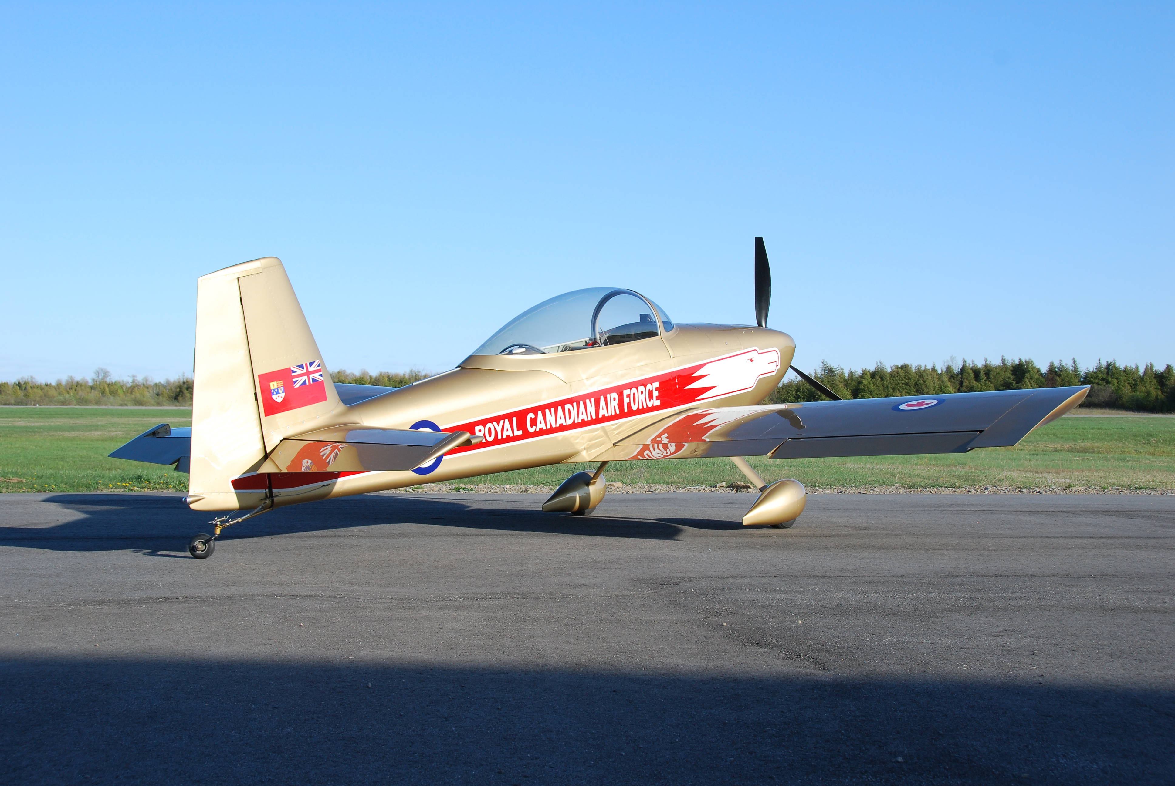
This blog covers the construction and flying of a Van’s Aircraft RV–8, built and flown by Kevin Horton.
I had thoughts of someday building my own aircraft from the time I was a teenager, but never took it beyond the fantasy stage until after arriving at Cold Lake, Alberta as a freshly minted test pilot. One of the other test pilots there was building an RV–4, and he told me fantastical tales of the performance and flying qualities. I did some research, and learned that Richard Van Grunsven (Van), had designed a very well loved all-metal single seater, the RV–3, followed by the two-place tandem RV–4, and the two-place side-by-side RV–6, all with tail-wheel landing gear. And then the RV–6A, with tricycle landing gear. All models had a good all-round performance and were reputed to have excellent handling. I was tempted, but the time wasn’t right. As always, there were one or two things to get done in life first, and then the time would be perfect.
A few years passed, and I eventually realized that as soon as you got one of those roadblocks out of the way another one appeared, and the “perfect time” never arrived. If you wanted to get something done in life, you just needed to get started.
One day I learned that Van had come out with the RV–8, which was two-seat tandem like the RV–4, but with much more baggage space, 10 gallons more fuel and a wider cockpit and instrument panel. I had visions of quite a bit of cross country flying, possibly in Instrument Flight Rules (IFR), so baggage space, fuel capacity and a large instrument panel were all attractive. This was the trigger I needed to get off my butt and start this grand project. I did a demo ride at Oshkosh in 1997, and was very happy with the aircraft, so I ordered the tail kit.
I looked at the tail kit as the litmus test - I would use it to see if I enjoyed the building process. If I did, I would continue. If not, I would sell the tail kit and drop the idea of building an aircraft. I found that the building process was very enjoyable, and was good way to relieve stress after a busy day at work. I carried on, doing a bit at a time, like the proverbial mouse eating the elephant. And one day, many years later, I had an aircraft. And it flew.
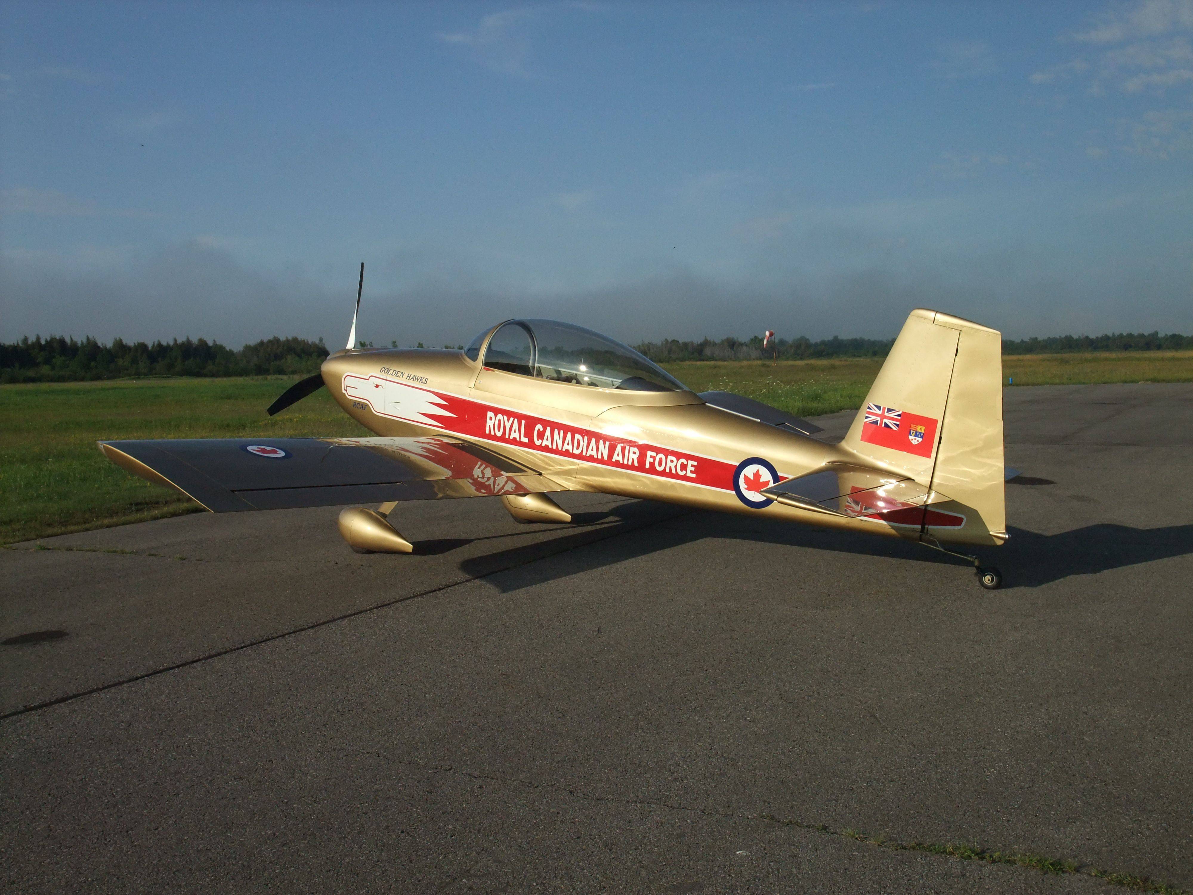 Construction started in the fall of 1997, and first flight was almost 11 years later in August 2008. The beautiful Golden Hawks paint scheme was finally done in the spring of 2010.
The aircraft has about 230 hours on it now (May 2013), and Terry and I have finally started to do some regular traveling with it. We took it to the huge EAA Fly-In at Oshkosh, WI in 2010 and 2011. I got to Sun n Fun in 2012, and we have flow it to Nova Scotia and Wisconsin several times. I try to fly the aircraft every week that I am home, if the weather cooperates.
There are a few more pictures of the aircraft in the C-GNHK Photo Gallery.
Scroll down for the latest detailed news.
RV-8 Sold
- Details
- Written by Kevin Horton
- Hits: 2041
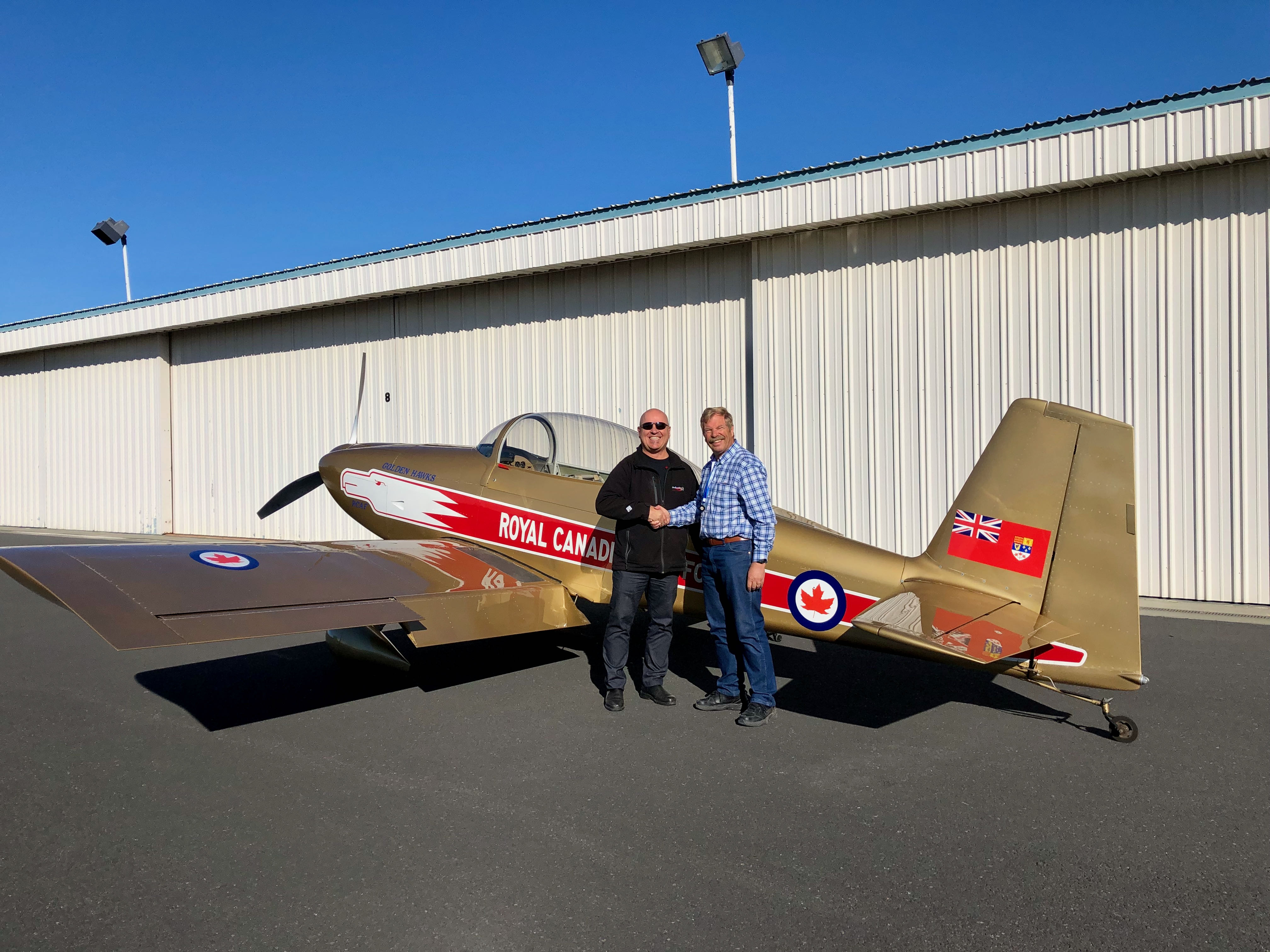
Today was a very bittersweet day, as I handed over the RV-8 to its new owner. He flew the aircraft north, to a new home back in Canada.
We will be moving to Green Bay, WI in a few weeks, where my wife has a large family. While we have greatly enjoyed flying the RV-8 for the last 13 years, a four seat cross-country aircraft better fits our needs for the next few years. After we arrive in WI, I hope to find (or create) a partnership that has several aircraft types, including a four seat cross-country aircraft, a single seat aerobatic aircraft and a high wing aircraft suitable for ops on short strips and skis in the winter.
The Trip to Moses Lake, WA
- Details
- Written by Kevin Horton
- Hits: 4595
We finally got the RV–8 to Moses Lake, with it arriving Tuesday afternoon. We didn't take the most direct route, as we wanted to visit family and friends on way across the continent.
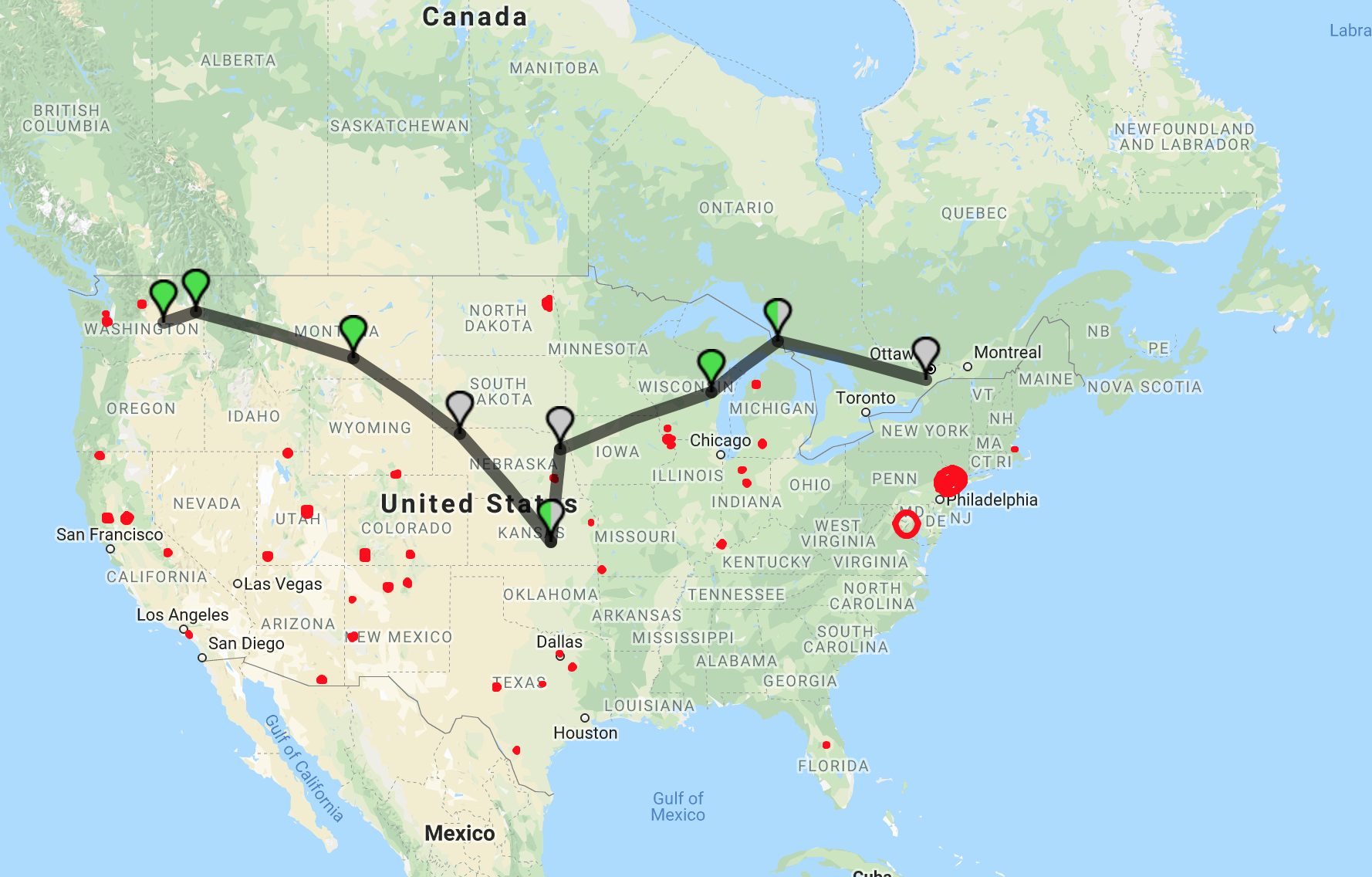
It took a few days to get the stuff in the hangar packed up to ship out west, then I flew to Green Bay, WI to meet with Terry, who was there visiting family. The importation paperwork at Sault Ste. Marie, MI took longer than I had hoped, but the US Customs folks were very friendly and helpful.
Next overnight stop was at Newton, KS, to visit friends in Wichita. Then it was Billings, MT for the next night. Billings has a great downtown, and I highly recommend it if you need a place to spend a night.
Sunday morning we left Billings, intending to do a quick gas stop in Coeur d’Alene, ID, and arrive in Moses Lake for lunch. But, the mountain weather didin’t cooperate, and we ran into low cloud a bit west of Helena, MT. We did a quick 180 and landed in Helena to wait for the weather to clear.
It turns out that the airport at Helena has a great place to cool your heels, Mustang Mickey’s, next to the self-serve fuel pump. It is a small hangar and pilot lounge owned by a local businessman and pilot. There is a full kitchen, shower facilities and four beds. Plus a courtesy car. The only rule is that you must fill the tank on the courtesy car after every use, so no one else has to pay for the gas you used. We went into town for lunch, and it cost $2 to fill it up afterwards.
Finally after a five hour wait in Helena, the weather reports suggested the low cloud had lifted, so we launched again, hoping to make the two hour flight to Moses Lake. But, life had other plans. As we passed overhead Spokane, I noted a strange engine indication I didn’t like, so we landed in Spokane rather than roll the dice on another half-hour of flying. There was no hope of finding any assistance to sort out the issue that late on a Sunday, so we got a one way car rental and drove home.
On Monday I drove to Spokane, and met with an A&P to troubleshoot the issue. We found that one cylinder had developed some sort of ring issue, and the excessive blow-by of combustion gases had blown a significant percentage of the oil out of the crankcase, leading to the engine indications I had noted. His borescope inspection found no sign that it would be unsafe to do the short flight to Moses Lake, once I had topped up the oil.
Tuesday, one of my coworkers flew me to Spokane, and I flew the aircraft to Moses Lake. The engine ran perfectly the whole way here, but I’ve grounded the aircraft until I’ve sorted out the issue with the cylinder. Now I’m beating the bushes looking for experienced assistance to help me sort it out.
Site Search Function Fixed
- Details
- Written by Kevin Horton
- Hits: 3931
I’ve fixed the Search function on this site.
I had noticed a couple of weeks ago that it wasn’t working, but couldn’t figure out why. Today, out of desperation, I read the documentation, and found that the content indexing had gotten fouled up when I moved the site to a new host. It was an easy fix once I knew what was going on.
Moved to Moses Lake, WA
- Details
- Written by Kevin Horton
- Hits: 4863
I’m way overdue for an update to this site, so here goes.
I was contacted by a friend in July 2017, who informed me that they were looking for experienced test pilots for the Mitsubishi MRJ program in Moses Lake, WA. I signed on to the program in September 2017, and immediately started a prolonged series of back to back courses to do all the steps required to obtain a Japanese Airline Transport Pilot License. This process kept me busy until Christmas.
Terry handled the packing and moving while I was off on training, and we set up house in Moses Lake in November. There was no free time to fly the RV–8 out there before winter hit, so it is in storage in Smiths Falls. I’ll take some time off in the spring to fly it west.
Moses Lake is fairly small town in a very dry area on a plateau between the Cascade Mountains and the Rocky Mountains. It only gets about 9 inches of rain annually on average, so there are usually blue skys. The airport was used as a B–52 base before Larson AFB was closed in 1966, so it has a very long (13,500 ft) and wide runway. The good weather, long and wide runway, and little air traffic make it a perfect place to conduct flight testing.
Toronto for Lunch
- Details
- Written by Kevin Horton
- Hits: 5554
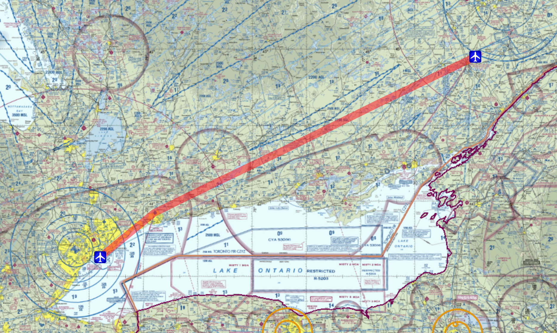 Today was a rare combination of good weather and Terry and I both being free of other commitments, so we flew out to Toronto for lunch. Toronto City Centre Airport (CYTZ), on Toronto Island, in the harbour right next to downtown Toronto, makes a great destination, as there are myriad nice eating places within walking distance once you take the ferry or walking tunnel to the mainland.
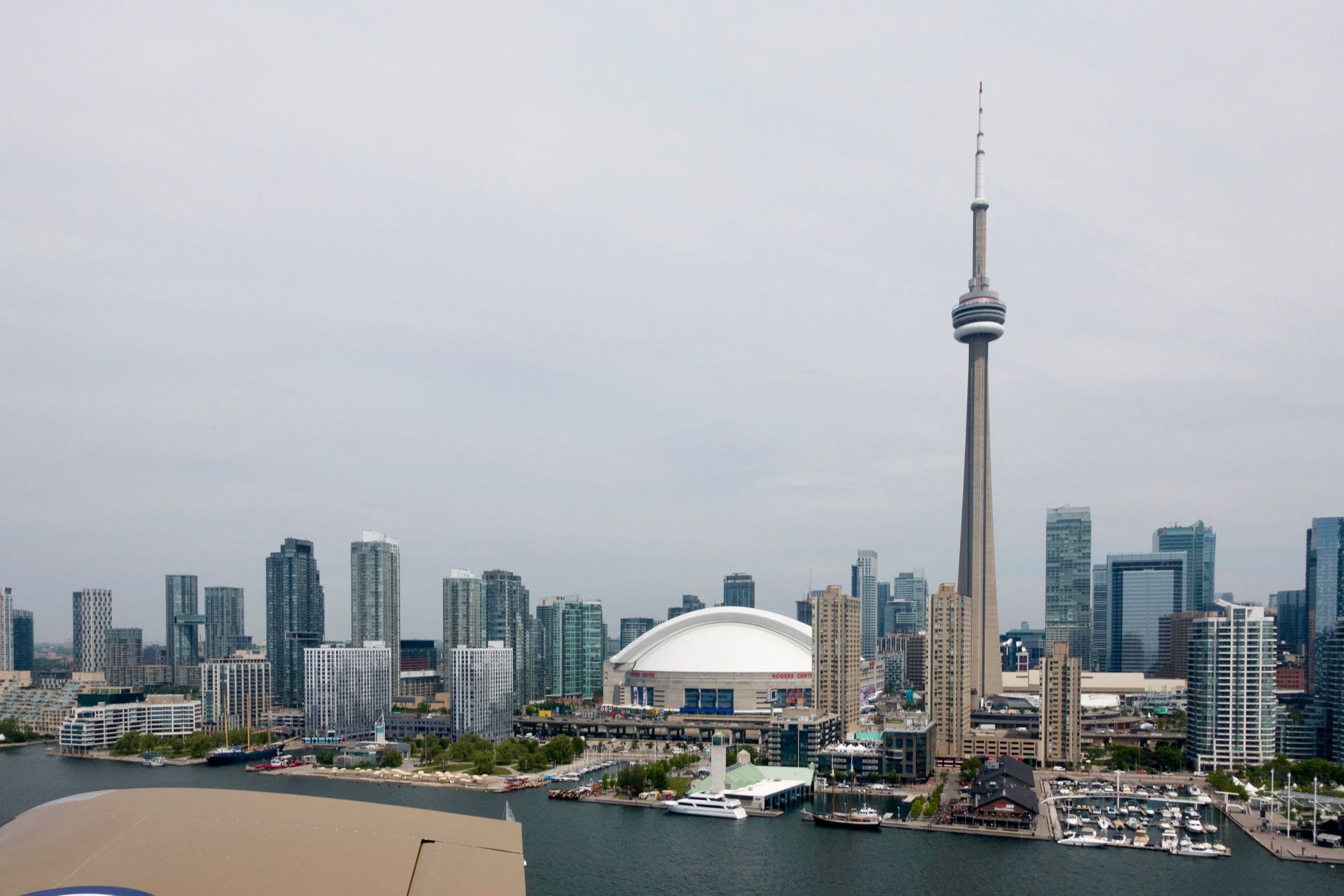 Final approach to runway 24 took as right by the CN Tower, Sky Dome and dozens of condo towers.
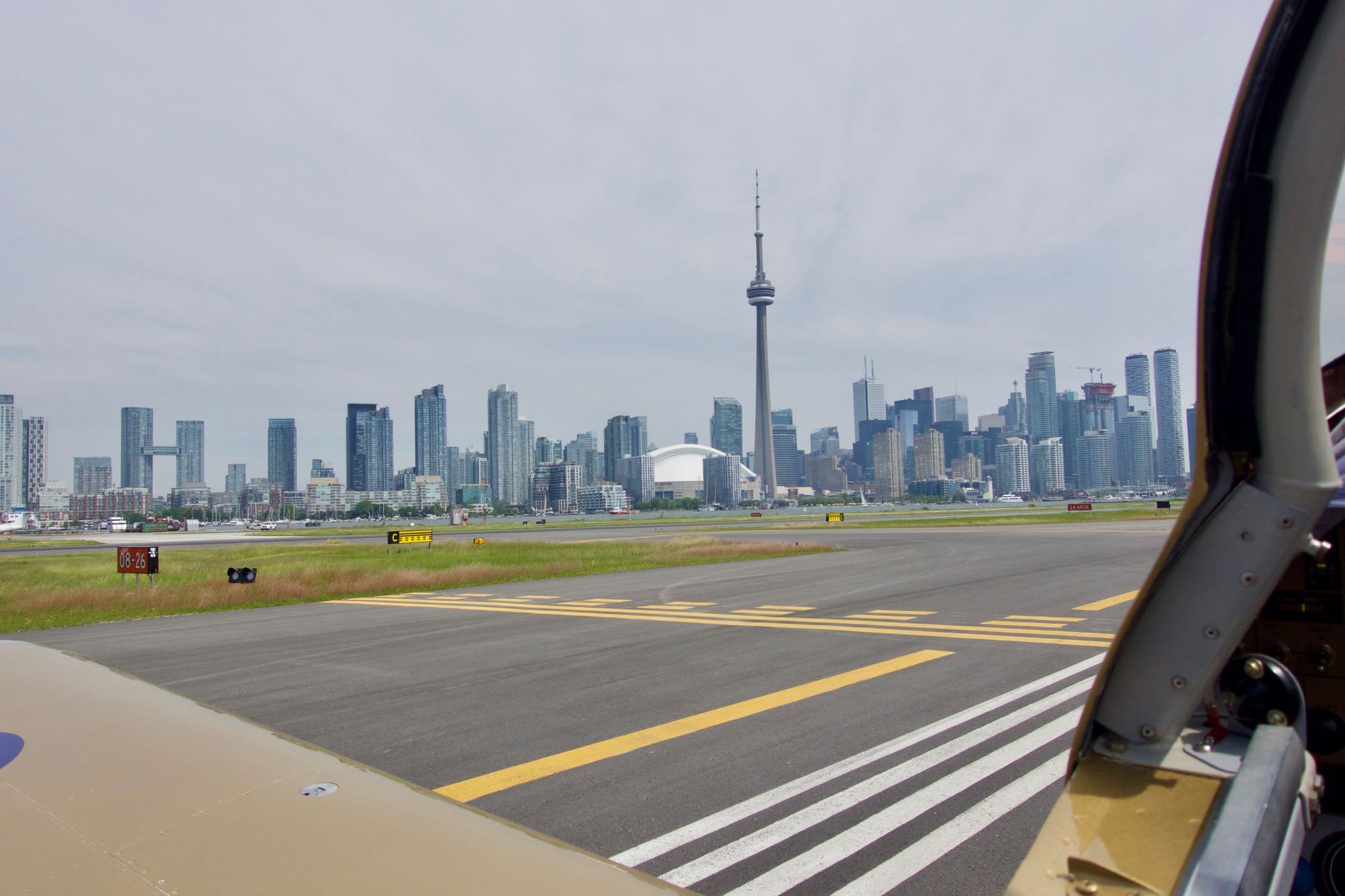 We had a great view of downtown Toronto while waiting to cross runway 26, after back tracking to the button of 24 (the taxiway at the west end of runway 24 was closed for construction).
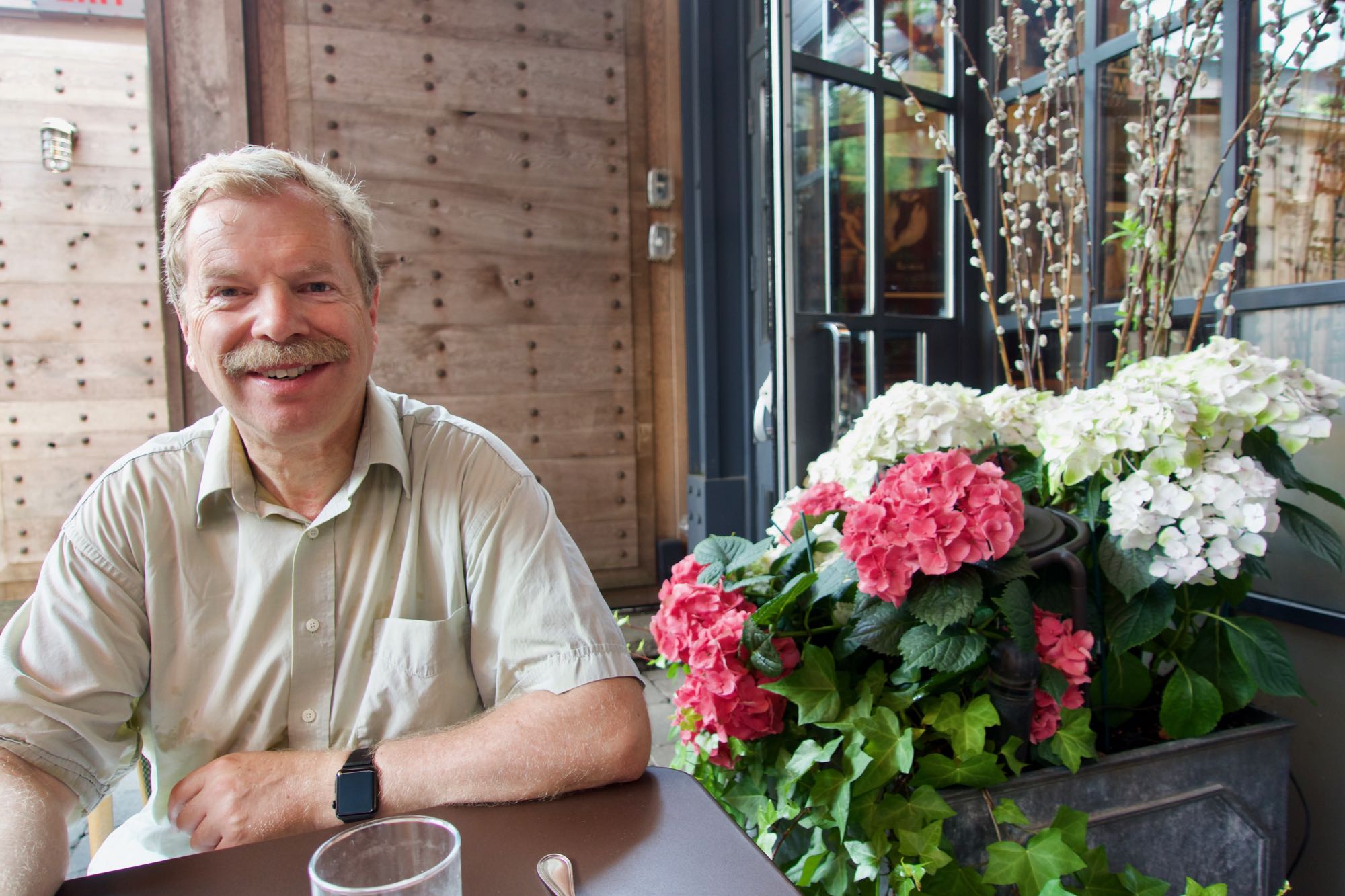 We had a fantastic lunch at Le Select Bistro, which is a great North American interpretation of a French bistro (the original version would have the tables jammed much closer together, to get twice as many customers in the same space, but otherwise it is pretty close).
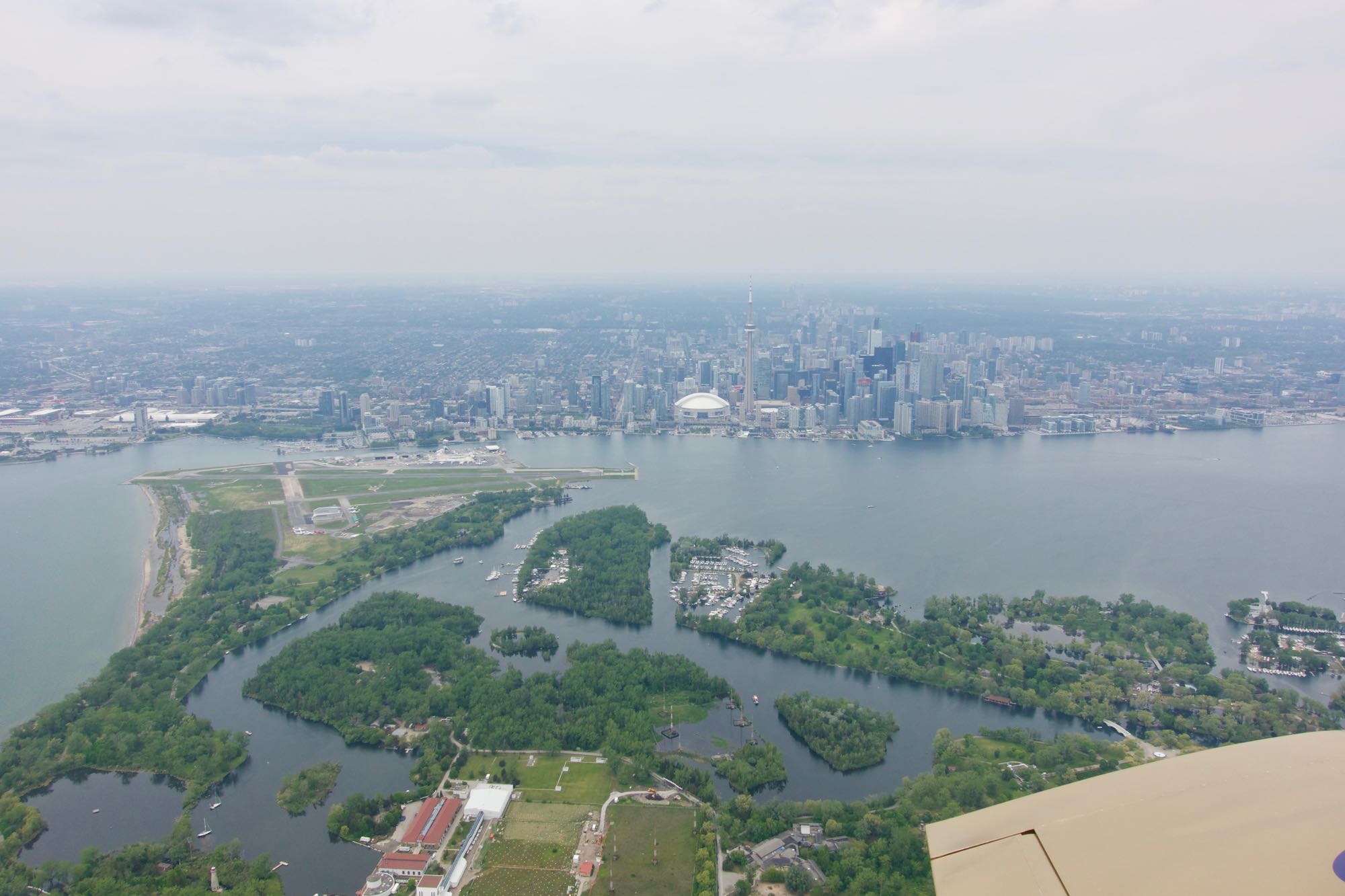 We had a great view of Toronto Island, the airport, and downtown Toronto after taking off on runway 24, then circling Toronto Island to head east.
Back home, on downwind for runway 24 at Smiths Falls (CYSH)
