Flap Inboard Lower Surface Machinations
- Details
- Written by Kevin Horton
- Hits: 5132
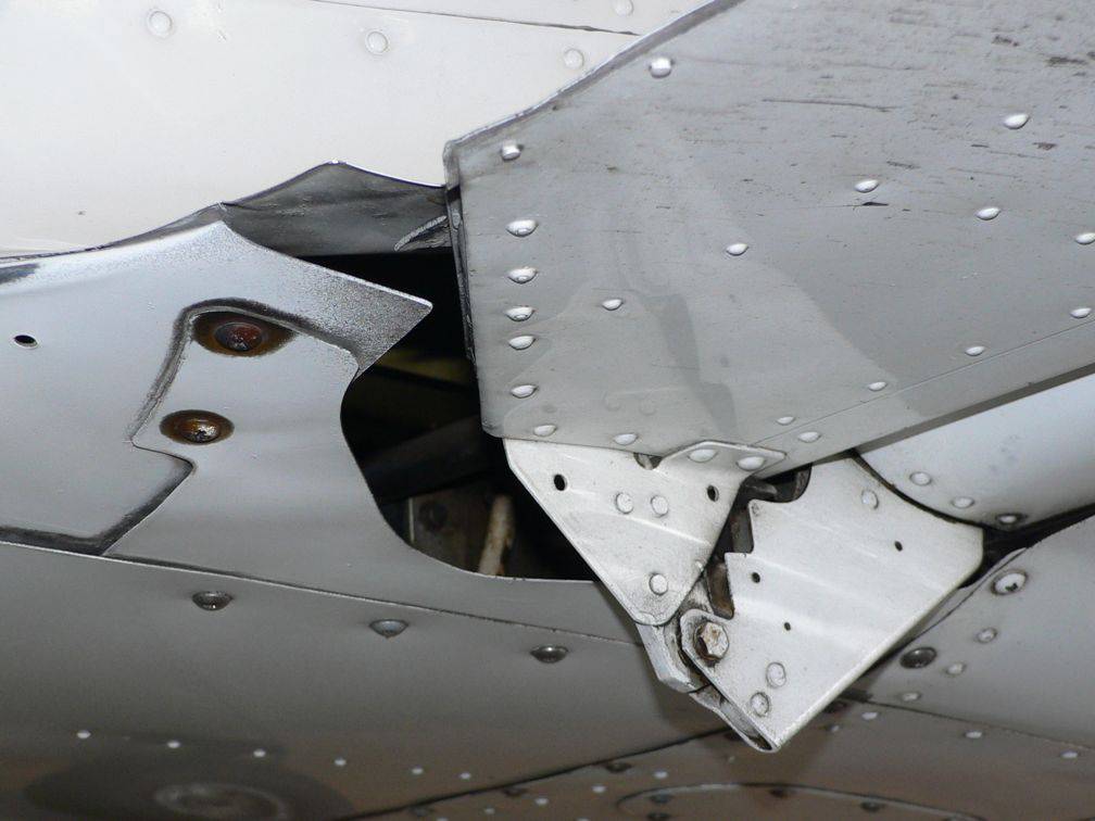
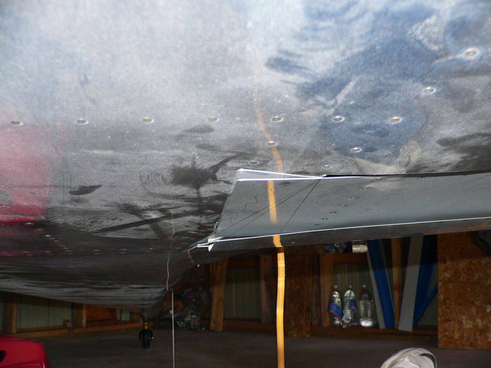 It is quite common to find that the inboard lower surface of RV-8 flaps do not match up well to the fuselage. This view is looking aft, at the inboard lower surface of the left flap, with the hinge line near the top of the picture. The forward part of the lower skin, not yet trimmed, sticks down quite a bit below the fuselage. The aft end of the trailing edge is sticking down below the fuselage fairing. The whole thing looks quite untidy.
I wasn't sure what I was going to do about this until I found Randy Lervold's description. Randy trimmed the inboard edge of the skin to match up against a seam in the fuselage skins, and he bent the inboard edge so it matched the fuselage. I was a bit troubled by the fact that Randy's solution had a small portion of the flap trailing edge sticking down perhaps a quarter inch below the flap to fuselage fairing. That would cost at least a hundredth of a knot, and looked less tidy than I wanted. So, I decided to "improve" upon his concept by trimming the upper surface skin a bit more, to allow the bend in the lower surface to start further outboard.
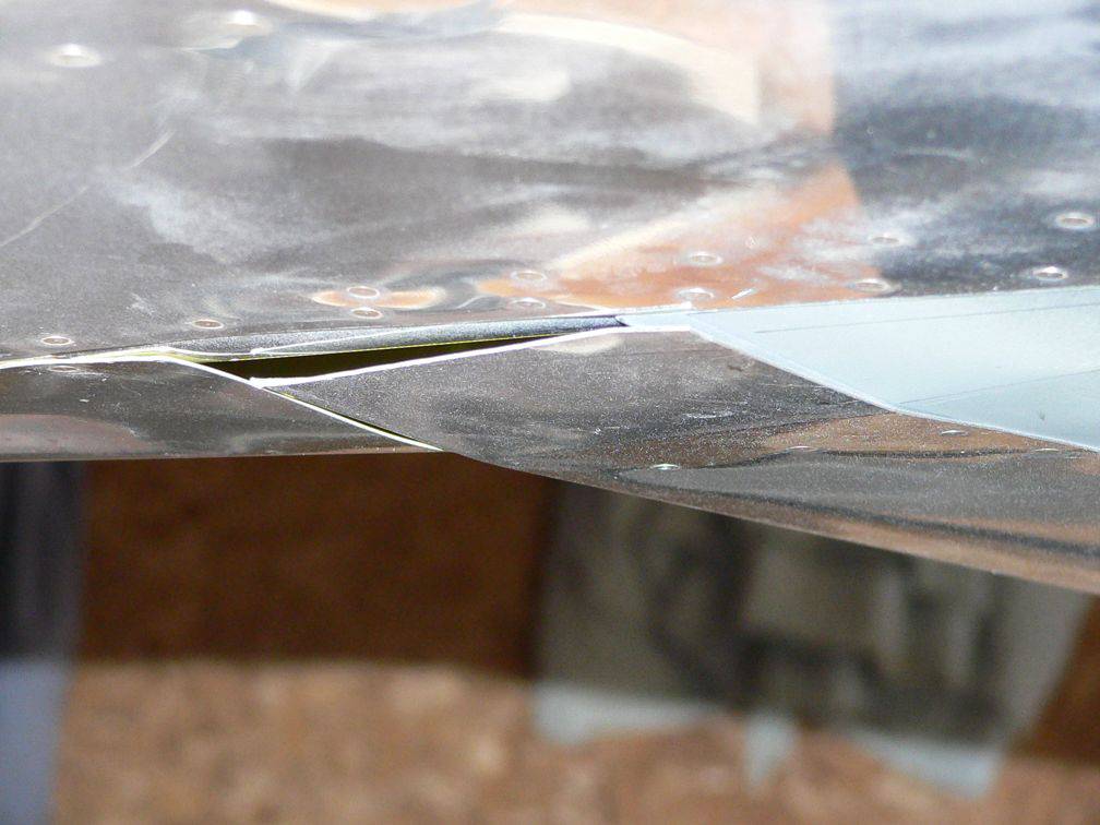 Once I trimmed the upper skin, and trimmed and bent the lower skin, I was very happy to see that it fit very nicely. But I was quite dismayed to find that the inboard portion of the lower surface skin was much less stiff than I had expected, due to the loss of support from the upper surface skin. Now I saw why Randy had trimmed his flaps the way he did. Drat. I should have simply copied Randy's idea, without trying to "improve" upon it.
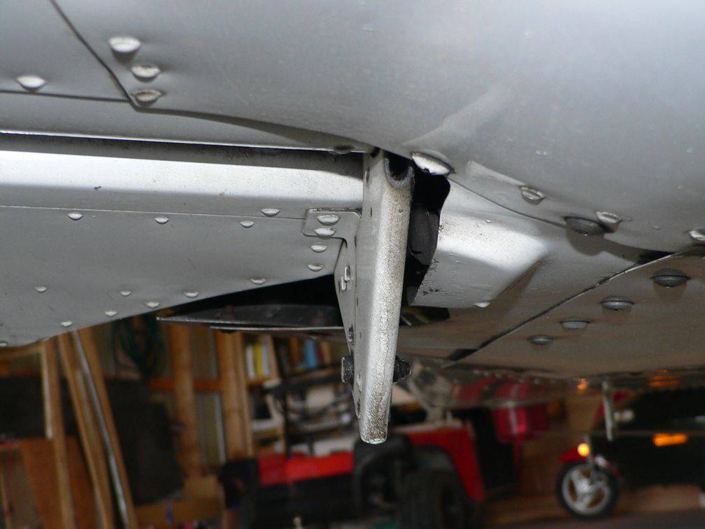
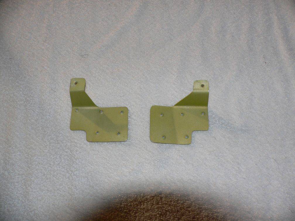 I did some serious head scratching, and finally fabricated reinforcements from 0.040 aluminum. The reinforcements attach to the inboard flap rib at the upper and lower rivets, and then extend inboard to support the lower surface skin. They appear to add more than enough stiffness.
 I need to add one more rivet to connect the two portions of the lower flap skin, as the two layers are spread slightly apart at the inboard end. I didn't get the right reinforcement installed today, as it turned out that one of the holes was in a slightly less accessible location, and I would need my pop-rivet dimple tool to dimple the flap skin, and it was sitting home in the basement. I also need to bring a different bucking bar so I can get the most outboard rivet on the lower surface of the reinforcements. Next work session.
 After spending many extra hours work because of my distaste for having part of the flap sticking down a quarter inch below the fuselage, I wondered how the flap to fuselage interface is done on other aircraft. There are two Mooney M20s in the hangar, so I peered under an M20F. I was amazed to see a huge hole between the inboard edge of the flap and the fuselage - the hole is about 8 x 4 inches, and must create a lot of extra turbulence.
 The hole between the flap and fuselage looks like it would act as a huge scoop, catching the air. Ugh.
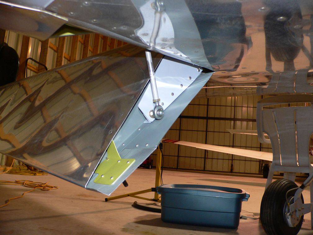
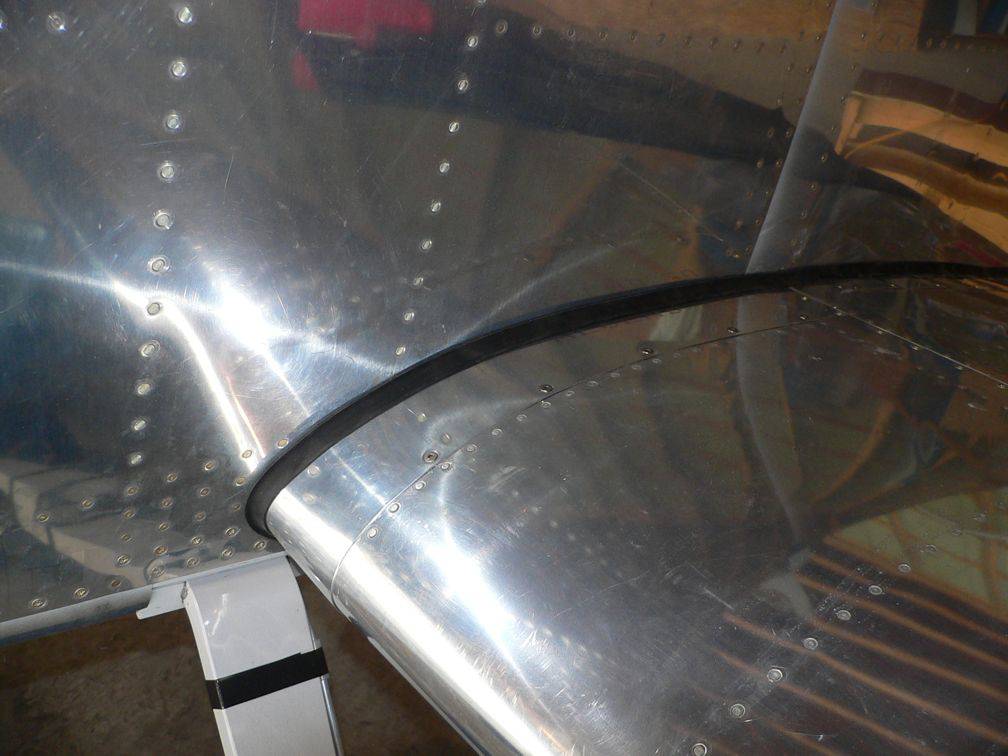 After installing the left flap reinforcement, I bolted the flap pushrod to the actuator, for hopefully the last time. Then I installed the left wing intersection fairing.
OAT Probe Working
- Details
- Written by Kevin Horton
- Hits: 3522
I got the OAT probe installed, and connected to the EIS 4000 back in mid-April before I did the last burst of road trips. The Grand Rapids OAT probe comes with six feet of wire, as I recall, and I understood that the wire could not be spliced [Update 26 June 2008 - apparently the OAT probe is a thermister, and the wire can be spliced. Thanks to Skylor Piper for noting my error, checking with GRT, and letting me know. I'm not sure why I thought it could not be spliced]. They will sell probes with custom lengths of wire, if requested. I knew that the standard length of wire would not be enough, so I made some measurements, estimated how long a wire I needed, and added a bit more just to be sure I had enough. When I ran the wire, I wanted to route it with other wire bundles, so it had some support, and those bundles made several detours to get around the passenger foot wells, the aileron pushrods, the front spar, landing gear boxes etc. As I ran the wire, the amount left was getting shorter, and shorter, and I became concerned that I might not have enough. When I finally got it all the way to the EIS 4000, I was very happy to see that I had three inches of extra wire.
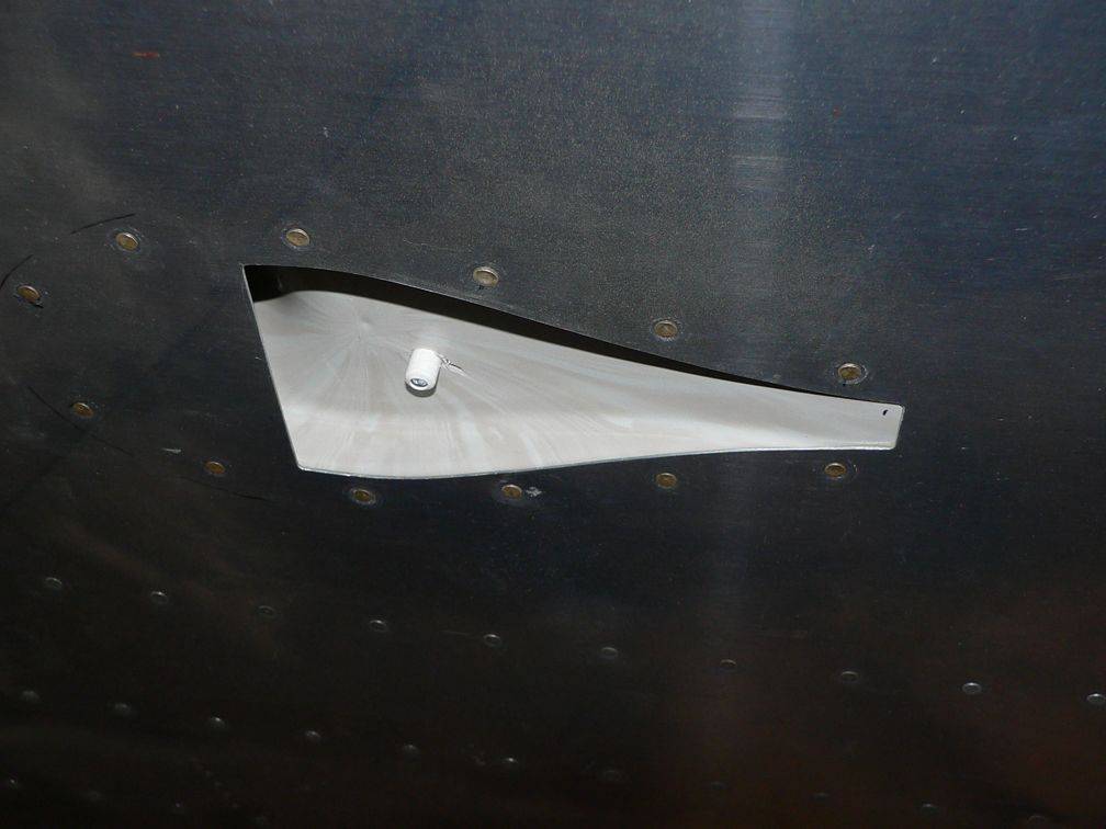 I screwed up when I drilled the hole in the under-wing NACA scoop for the OAT probe - I went straight to the final size hole, and that large drill dug into the plastic and cracked it. I fixed it with epoxy today. I should have started with a small hole, and worked up in small increments. I put the OAT probe over to one side, to leave room in case I later decide to add an OAT probe for the Dynon EFIS.
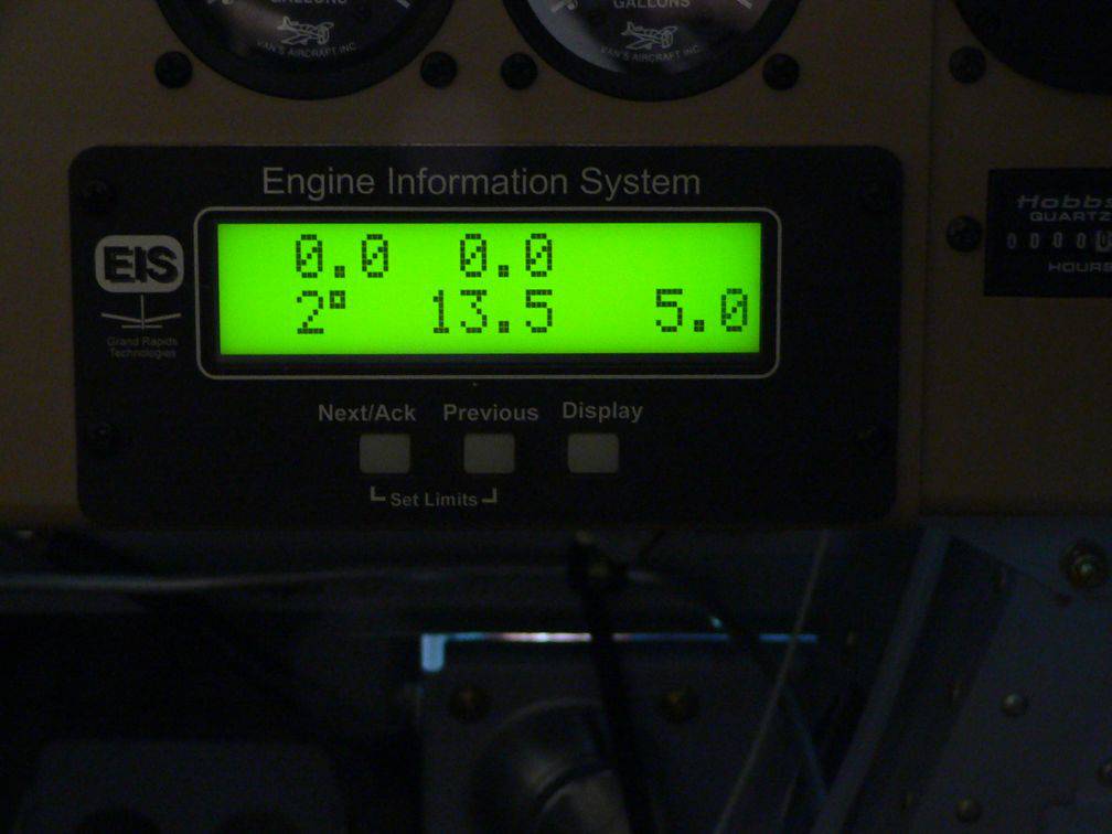 The OAT is displayed at the bottom left on the EIS 4000 screen - it is showing 2°C, which compared well with the temperature shown on the thermometer in the hangar.
To Do List - Apr 2008
- Details
- Written by Kevin Horton
- Hits: 4295
RV-8 To Do List
Final AssemblyAfter 1st Flight
Sheet 1: Final Assembly
| Date | Fixed | |
| 26 Mar 06 | Remove exhaust port plugs & tighten exhaust connector links. | |
| 27 Aug 02 | Prop – Inspect blades in spinner area. 2 small nicks, one on face of blade 96 and one on back of blade 95. | |
| 27 Aug 02 | Prop – Polish and repaint the 2 small nicks above. | |
| Front Seat – Make seat riser to put under parachute? Maybe not needed. Check after purchasing a helmet | ||
| 07 Mar 07 | Install ELT antenna | |
| 08 Oct 07 | Put spiral wrap on Hall Effect Sensor wires | |
| 24 Jul 07 | Review FT data recording script. Fix list of snags identified at top of script. | |
| 06 Sep 07 | Install front seat belts | |
| 07 Jul 05 | Install TVS on defrost fan | |
| 09 Aug 06 | Oil separator – install breather line on exit | |
| 02 Dec 06 | Fabricate computer hold down tray | |
| 02 Dec 06 | Finish engine cooling plenum | |
| 27 Jan 07 | Install safety wire on baffle cylinder wrap-arounds | |
| 26 Feb 07 | Secure wiring ahead of FW | |
| 06 May 07 | Install EI plug wires | |
| 12 Aug 07 | Put heat shield foil inside cowling bottom. | |
| 20 Aug 07 | fill and bleed brake system | |
| 08 Oct 07 | Install wing walk anti-slip | |
| 19 Jan 08 | Retorque tail wheel axle bolt, in warmer weather, after greasing it. | |
| 17 Feb 08 | Joggle IB end of lower flap skin | |
| 18 Apr 06 | Flaps – Add rivets on lower surface to join upper and lower skins at inboard end, if required. | |
| 17 Feb 08 | Install bolts at top of flap pushrods | |
| 17 Feb 08 | Reinstall COM 1 antenna | |
| 17 Feb 08 | Install new Xpdr antenna | |
| 18 Feb 08 | Install pitot heat CB before final inspection | |
| 22 Mar 08 | COM 2 functional test | |
| 22 Mar 08 | Install screws in L wing tip (after COM 2 functional test) | |
| 11 Apr 08 | Put edge guard on LG box brace @ Narco coax area | |
| 13 Apr 08 | Check magneto timing | |
| 13 Apr 08 | Fill divot in under-wing NACA scoop. | |
| 27 Apr 08 | Replace 2 valve covers | |
| 27 Apr 08 | Pull two cylinders and inspect inside engine | |
| 27 Apr 08 | Weight and Balance | |
| 01 Feb 02 | EI – Time EI and torque the bolts holding the sender to the accessory case | |
| 17 Jun 01 | FI Servo - Remove plastic covering the intake | |
| 27 Jan 07 | Retrieve red “straw” from fogging spray can from front left cylinder | |
| 30 Mar 08 | Put break-in oil in engine and pre-oil it | |
| 16 Feb 02 | Starter Solenoid – Tighten nuts attaching the cables | |
| 27 Apr 08 | Full power engine run | |
| 27 Apr 08 | Final inspection | |
| 27 Apr 08 | Install cockpit floor |
Sheet 2: After 1st Flight
| Date | Fixed | |
| 01 Apr 06 | Fabricate and install ELT cover | |
| 26 Jan 07 | Fabricate and install pubs holder on canopy frame | |
| 26 Jan 07 | Replace CDI with Dynon D-10A as EHSI | |
| 15 Oct 03 | Rear Shoulder Harness – Secure ends of belts | |
| 03 Dec 06 | Fabricate flap pushrod boots | |
| 08 Jul 07 | Run wires for Dynon HSI34 and second D10A | |
| 11/10/07 | Install Velcro for fabric panels in cockpit | |
| 13 Nov 06 | Install flap pushrod boots |
On the road again
- Details
- Written by Kevin Horton
- Hits: 4054
In late March and early April I closed off a number of small items, and started cataloging all the non-building type things that had to happen before the aircraft is legal to fly. Such as altimeter and altitude encoder checks, ELT check, etc. I spent quite a bit of time tracking down the details of the required altimeter and altitude encoder checks - they are very well hidden. CAR 605.86(1) says the aircraft must have an approved maintenance schedule, which conforms to the Aircraft Equipment and Maintenance Standard (a.k.a. CAR 625). CAR 625.86 says that as part of the approved maintenance schedule, owners of non-commercial small aircraft must comply with Appendix C to CAR 625, and in there we find the details of the required ELT, altimeter, transponder and altitude encoder checks. It looks like Woodlawn Instruments are the best local place for the altimeter and altitude encoder checks, and Canadian Airmotive Avionics are the best place to have the ELT and transponder checks done. Canadian Airmotive Avionics will even come out to Smiths Falls to do the portion of the transponder check that must be done on the aircraft.
I tracked down a set of supposedly accurate digital scales, and the tools I need to pull two cylinders and do a borescope inspection for internal engine corrosion. I need to get two cylinder gasket sets though.
I was on the road the last two weeks (one week in London, ON, home for 35 hours, then one week in Toulouse, France), so today was the first work session for about 2.5 weeks. Three hardware orders came in while I was on the road, so I was able to finish off several small items that were on hold for lack of small parts. I'm still a bit jet-lagged, as I got back from France on Friday afternoon, so I ran out of steam mid afternoon and came home.
Today I did some scouting around the airfield looking for some sloped terrain to help get a suitable nose high attitude for a fuel flow test. It looks like there are potential places to do this test, including one across the ramp from the fuel pumps, behind the "Beech Hangar".
I hope to be around town for the next several weeks, so will be pushing hard to close off all the remaining items . I'm not too many weeks away from doing the first engine run, the weight and balance, etc, then having the final inspection.
Fuel Line Rebuilt
- Details
- Written by Kevin Horton
- Hits: 3978
I had a good work session at the hangar today. In the morning I closed off a bunch of small items, and in the afternoon I attacked the fuel line from the right tank to the fuel selector. I originally made that fuel line a long time ago, then when I installed the wing leveler servo I discovered that the location I chose for it interfered with the way I had bent the fuel line. So, I pulled the fuel line out and put it on my To Do List. Well, today I finally got to that item. It was a pain in the butt to get it sorted out, as now that all the wiring is in, it made it impossible to manoeuvre the whole fuel line in place. I had to make it in two pieces, with an AN815 union to connect them together. It took quite a bit of screwing around to get all the bends in the right place - I destroyed a hanger so I could use the wire to do trial templates. But in the end it worked out pretty much perfectly. I just need to make some spacers to put between the wing spar and the Adel clamps so the AN815 union doesn't press on the spar.
I'm quite satisfied with the progress I've made lately. I still have quite a bit of work to do, but I am working my way through the remaining items on the To Do List at a good rate. This weekend I got that list down to less than one page, and I got one of the more worrisome items (that fuel line) off the list. Barring some strange event, I really should be able to do the first flight sometime this summer. I am really, really hoping to get it done in time to allow me to take the aircraft to the annual Oshkosh fly-in, but there are a whole bunch of ways that this plan could fall apart.
Dynon Autopilot
- Details
- Written by Kevin Horton
- Hits: 6945
 Dynon has been working on an autopilot for quite some time, but they've kept the details very close to their chest. Well, the information is finally starting to emerge, and it sounds very, very enticing. The lead-in image is an advertisement that appeared in the electronic version of the latest Kitplanes magazine.
Each servo is $750, and the interface can be via a Dynon EFIS, or via a dedicated AP74 control panel. The autopilot can be slaved to the bugs that are set on the EFIS. That means that I could add a pitch axis autopilot to my aircraft for $750, without having to sacrifice any panel real estate. The only downside is that the servos are similar to those from TruTrak, in that there is some drag on the flight controls even when the autopilot is not engaged. Those that have TruTrak autopilots claim that while the drag from the servo can be felt on the ground cannot be perceived in flight.
I'm putting any work on my pitch axis autopilot project on hold until I learn more about the Dynon autopilot. Assuming I can live with the servo drag, it is hard to go wrong for $750.
Update 28 Mar 2008 - Dynon now has autopilot information posted on their web site.
