Gotchas
The combination of parts and instructions create a few potential problem areas that builders should be aware of. Fortunately, previous builders provided a lot of advice on what areas to look out for, so I was able to avoid most of the pitfalls listed here.
Note - The following info is based on fuselage parts that were shipped in January 1999, and on revision R2 to DWG 24. Some of this information may not be valid with later fuselage parts, later revisions to DWG 24 or amendments to the Construction Manual.
Read on for more info.
 Fit of LG Boxes in fuselage - The instructions say to drill and cleco the F-802A, B, C, E & F together on the workbench. Some builders have found that the LG Box does not fit correctly when they place it in the fuselage. It seems that the method suggested in the instructions is not accurate enough. It is recommended that the F-802C not be drilled and clecoed to the F-802E until after the F-802 A & B are drilled and clecoed to the F-820 and the F-802G & H, with the whole assembly in place inside the fuselage. That way you can set the fore and aft location of the top and bottom of the LG box independently. If you have got the F-802C drilled and clecoed to both the F-802E and the F-802F, the box is no longer flexible. You can shift the whole thing fore and aft, but it the top and bottom don't fall into place at the same time, you are stuck.
- F-802G & H Outboard end - The second most outboard bolt hole in the F-802G & H will interfere with the little angle welded inside the Wd-822, if you put the bolts in the locations called for in the plans. The best answer appears to be to not drill those holes until you can check where the holes will go. I ended up putting the hole in the same distance from the end of the angle, but raised it up to 25/32 above the bottom. I can get a nut and washer on the bolt, but I had to relieve the piece of angle slightly so the end of the bolt doesn't hit it. Don't trim the width of the F-802G & H until you figure out where those holes should be, as you might have to raise them, which could leave you short on edge distance if you have already trimmed the width of the F-802G & H.
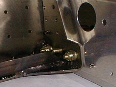 Here you can see the middle bolt (without a nut), just touching the steel angle inside the landing gear box. This is with the bolt moved up as I described. The interference would be much worse with the bolt in the location called out in the plans. The other two bolts are in the location called out in the plans, and there is no problem.
Note - I am told that DWG 24 r3 addressed this issue by raising the second most outboard bolt to 7/8 above the bottom. This would have worked better than the 25/32 that I tried.
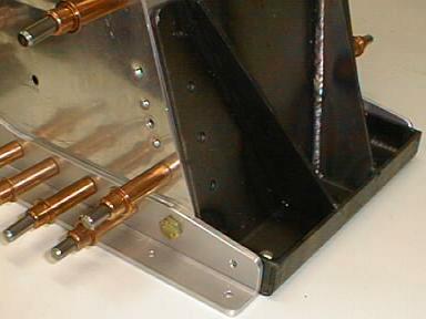 F-802G & H Inboard end - Some builders have reported that the inboard end of the F-802G & H is too short. I left the inboard end of the F-803G & H longer than shown on the plans, and didn't drill the holes until I put the Wd-813 in place to see where they would go (the nominal length of the F-802G & H is 8.5 inches, but the material supplied is long enough to make them 9 inches long). I found that the plans location for that hole was perfect, and I ended up trimming the inboard end of the F-802G & H exactly as shown on the plans. The Wd-813 will stick out a bit past the end of the F-802G & H, but I was happy with the appearance, and the part would be heavier if I trimmed it to the same shape as the Wd-813. I hate unnecessary weight.
- Wd-822 Edge Distance - Some builders have reported problems getting acceptable edge distance on the holes for the rivets, bolts, etc that go from the Wd-822 to the side of the fuselage. Some of these problems may be due to not getting the tabs on the lower edge of the F-820 Forward Side Skin exactly on the vertex of the F-843 Forward Lower Longeron. If the F-820 skin is not correctly located, the fasteners that go through the pre-punched holes will end up in the incorrect location on the Wd-822, and that can mess up the edge distance. Once you've got the F-802A drilled and clecoed in position inside the forward fuselage, it is recommended to hold the Wd-822 in position, and have a helper mark the position of the prepunched holes on the "wings" of the Wd-822. It is much better to discover an edge distance problem before drilling the holes than after.
Plans sheet 24 gives the minimum edge distance for the rivets on the lower side of the Wd-822 "wings", but there is no info about edge distance for the rivets on the upper side. It looked like the edge distance on the upper side of my Wd-822s would be between 5/32 and 3/16 inch. This concerned me, because the minimum edge distance for holes in aluminum is 2 x the rivet diameter, or 1/4 inch for this size rivet. I didn't know what the minimum edge distance would be for the steel Wd-822, so I sent an e-mail to Vans, and did some digging in my old engineering texts.
Holes in material cause stress concentrations, which is a big problem in aluminum because high stress gives a short fatigue life. Aluminum has a fatigue problem at any level of stress - the lower the stress level, the more cycles it will take to break it, but you will get fatigue at any stress level if you go for enough million cycles. Things are different with steel - steel does not have a fatigue problem, as long as the stress is lower than a critical value. The big issue with steel is simply making sure that the static strength is high enough to take the loads.
I discussed the edge distance question with Ken Krueger, an engineer at Vans. He told me that the nominal edge distance for the rivets on the top of the "wings" was 5/32 inch. The loads were not a big problem in this area, because the landing gear loads are pushing up on the Wd-822, which means that the rivet is at no risk of tearing out the edge of the steel. I was even more concerned about the small edge distance on the 3/16 bolt that the F-863 fuel tank attach bracket uses, but there again, the load are in the wrong direction to tear the bolt out.
On my landing gear boxes, the edge distances on the left Wd-822 turned out to be exactly the nominal values. But, on the right one, the forward rivet hole on the bottom "wing" ended up too close to the forward edge of the "wing" (5/32 inch edge distance). That hole is supposed to get a #8 flat head bolt, but I'll put a 1/8 rivet in there, and drill another hole between this one and the next one aft for the bolt.
- Location of AN509 screws - Several builders reported that two of the AN509 screws which go from the F-820 Forward Side Skin into the Wd-822 interfere with two of the bolts that go from the F-802G & H into the landing gear box. I can confirm this.
 Plans drawing 28 (at revision R5) shows two rows of AN509 screws at the bottom of the Wd-822. Two of the holes in the lower row are shown as being AN426 rivets. Several earlier builders reported that you could get around this problem by swapping the rivet location with the screw that is just outboard on each side of the landing gear box. I did this mod on my LG box.
CAUTION - When I installed the landing gear legs, I discovered that the AN509 screw now may interfere with getting a socket on the nut on the big NAS bolts that will come into this area from below, holding the U-803s (see DWG 35).
I advise that you don't swap fastener locations if possible, to avoid the domino effect that I got into. You may be able to put the fasteners where Van suggests by using MS21042 reduced dimension lock nuts on some of them. These nuts are much smaller, and you should be able to use a slightly shorter AN509 screw or AN3 bolt. See the Wicks Catalog for a picture.
If you swapped the rivet and screw locations, and now cannot get a socket on the nut on the NAS bolts, I see four options:
- insert the NAS bolts the other way, with the nuts on the bottom. The cover will have to be shortened, as the bolt ends will protrude, but that area gets covered with a fairing anyway. I'll need to remove several AN509 screws to get the bolts in, but I can put them all back afterwards.
- Put an AN426 5-X rivet in place of the AN509 screw. You lose a tiny bit of strength, but there are a lot of fasteners in that area, so I suspect the loss of strength is in the noise. Anyone thinking about using this option should discuss it with Van's first.
- Put a CherryMax rivet in place of the AN509 screw. This has more strength than option 2, but I'm not sure how big the pulled head is on the rivet. It might be long enough to still get in the way. Anyone thinking about using this option should discuss it with Van's first.
- Remove the AN509 screws, and replace them after the NAS bolts are torqued. I'm not yet sure if I could get all the AN509 screws back in, and they would have to come out every time you retorqued those bolts. Not fun.
- Ground adjustable rudder pedals - If you are installing the optional ground adjustable rudderpedals (the ones that can be mounted in four different positions, given some tools and some time) look at theplans sheet that comes with the option kit. You have to countersink the most inboard rivet hole in the F-802G -I am talking about the row of rivets that go from the F-802G to the floor, not the ones that go from the F-802Ginto the landing gear box.
- Rear seat rudder pedals - The rear seat rudder pedals have a bracket that bolts to the back sideof the F-802H. Mark Goldberg pointed out that it is much easier to match drill the inboard hole in the bracketwith the landing gear boxes on the work bench than if you wait until the landing gear boxes are installed inthe fuselage.
- Removable F-802C - Mark Goldberg has his RV-8 flying already. He commented that the landing gearboxes are so full of stuff (control cables, brake lines, fuel vent lines, etc) that it is very hard to get atthe landing gear bolts to retorque them. He said that it he did it again, he would install the lower part ofthe F-802C with #8 screws and locknuts instead of rivets, so he could peel it back to improve the access insidethe landing gear box.
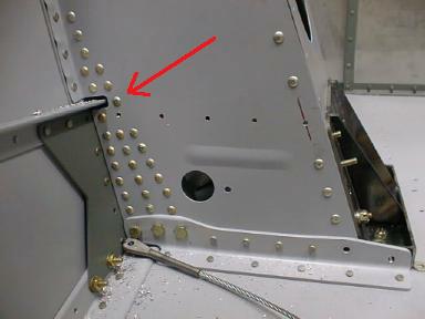 Interference with F-802P - I didn't discover this problem until much later, when I wasinstalling the F-802P angles, which mount to the rear face of the F-802B. On my parts, the F-802P interferedwith one of the rivets that attach the F-802B to the Wd-822. See the red arrow in the picture. For somereason, the rivet placement in the sea of pilot holes in the F-802B on my parts differed from that shown onthe plans. I would have been OK if the parts had been like the plans. As it was, the head of the offendingrivet interferes with the upper edge of the F-802P angle. I had to do some creative carving on the F-802P toallow it to sit flat against the F-802B. If your parts are like mine, I recommend that you simply leave thathole empty. There will be another rivet below it, holding the F-802P to the F-802B and the Wd-822.
 The top of the outboard end of the F-802P angle has to sit 0.063 inch lower than the top of the F-844longeron. If you have a rivet head that would interfere with an angle in that location, you have aproblem.
- Also see the landing gear box notes and photos on Larry Bowen's web site.