Russ Erb
Originally published September - October 1994
So How Do We Calibrate the Instruments?
Necessary Equipment
Setup
Data Collection
Data Reduction: Altimeter
Data Reduction: Airspeed Indicator
Sample Calculations
Pitot-Static System Leak Checks
Example Data
Picture yourself: You're rapidly approaching completion of your domestically produced aerospace vehicle, and you're studying up on how to run the flight test program. You are convinced by the plethora of reading materials that your flight test data will only be as good as your Pitot-static measurements. After all, virtually all measurements depend on knowing your airspeed and altitude. Why even the ubiquitous FAA Advisory Circular AC 90-89 "Amateur-Built Aircraft Flight Testing Handbook" (a well written guide in what to do, but sorely lacking in telling you how to do it!) talks about Pitot-static position error and a little bit on how to determine it (by use of the speed course method).
You may see various texts referring to position error or position correction and using the terms interchangeably. Strictly speaking, to find the "true" answer, an "error" is subtracted from the instrument reading. Similarly, to find the "true" answer, a "correction" is added to the instrument reading.
However, there is another error in your Pitot-static system that you need to determine. Fortunately, it is fairly easy to determine. Where is it, you ask? You may find this hard to believe, but that airspeed indicator and altimeter you just dropped $700 or more to Wicks for are not perfect! No, you didn't buy the cheap versions. It is just impossible to build a perfect instrument due to the limitations of real world physics (the physicists keep the massless rods and frictionless pulleys under lock and key).
Why are the instruments not perfect? There are several reasons. The scales may not be printed in exactly the right place, or the face may have moved. The gears in the instrument may not be sized perfectly. But most of all, friction still exists. We are trying to measure minuscule changes in pressure, which means the force exerted by the bellows in the instrument is also minuscule. Even with the best jeweled movement, there will still be a minute amount of friction opposing this minute force. As such, if the instrument is moving up (indication increasing), the needle will stop just below the "proper" value. Likewise, if the instrument is moving down (indication decreasing), the needle will stop just above the "proper" value. This difference in reading depending on which way the instrument is moving is called "hysteresis."
The airspeed indicator and altimeter are both pressure gauges. The airspeed indicator is a differential pressure gauge, and the altimeter is an absolute pressure gauge. Therefore, if we can apply a known pressure to the gauge, we should be able to calculate what the instrument should have indicated. Then we compare what the instrument should have indicated with what it did indicate to determine the instrument correction.
So when I say a "known pressure," do you have visions of a complicated, expensive laboratory instrument costing thousands of dollars and requiring a major chapter fund-raising drive to purchase? If so, you need to learn to think simple. All you need is a clear plastic tube and some water, and you can create a manometer, a precision pressure measuring instrument requiring no calibration. Manometers have a great history, being used for many years to measure pressure in wind tunnel experiments (and still used in some application). This method is based on the idea that manometers can not only be used to measure pressure differences, but to create them as well.
I developed this technique to calibrate instruments as part of a research project here at the U.S. Air Force Academy investigating the climb performance of aircraft towing gliders.
To pull off this calibration, you will need a little bit of stuff:
The vinyl tube can be found at Home Depot in the plumbing area. The vacuum hose, hose adapter, and hose clamps can be found at your local auto parts store. The hose adapter is a plastic piece used for joining vacuum hoses together, and has multiple diameters, each with ridges for holding the tubing on. Be sure to get one that will fit the vinyl tube on one end and the vacuum hose on the other end. Use the hose clamps over the adapter as required to get a good seal. The large binder clamps can be found at an office supply store. These are the big spring steel clamps for holding large bundles of paper together.
[Ed. Note: To be continued next month...you'll need the time to buy this stuff and get ready for the next installment!]
[When we left our story last time, our heroes were rummaging through one garage sale after another looking for tubing, vacuum hose, funnels and paper clips with which they could construct an instrument calibration apparatus. Unfortunately, due to space limitations in last month's newsletter, the device they built bore an uncanny resemblence to a still. Let's watch as they continue with their...*hic*...their instrument...*hic hic*...calibration device!]
The setup is simple in principle, but can get complicated in practice. Figure 1 shows the basic setup. Attach the board to something that will hold it vertical. I attach mine to the side of a ladder. Use the level to ensure the board is vertical. I like to cover the board with strips of 2" wide masking tape so that I can write on it, and remove the writing by just pulling off the masking tape (or adding another layer!). You can attach the tape measure to the board now or do it later during the data recording step. Be sure to put the zero end of the tape measure at the bottom, and flip the case of the tape measure over the top of the board. A couple of pieces of tape can help keep the tape measure in place.
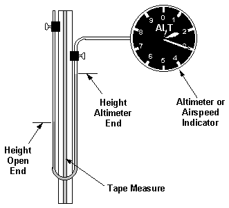
Figure 1. Manometer Setup
Attach the clear vinyl tubing to both sides of the board with the binder clips as shown in Figure 1. Insert the vacuum hose adapter in the end of the clear vinyl tube to be connected to the instrument being calibrated. Use a small hose clamp to ensure a good seal. Some Vaseline on the adapter might help get a better seal. Push the vacuum hose over the other end of the adapter.
Spread the end of the paper clip and stick it in the open end of the clear vinyl tube. Now place the funnel in the open end of the clear vinyl tube. The purpose of the paper clip is to create a small opening between the funnel and the tube to let air out as the water is poured in. Pour the water into the tube. Be sure you have a long enough water column in the tube for the maximum height you plan to test the altimeter. When I did this, to reach 12,000 feet on the altimeter at a local pressure altitude of 6500 feet required 61" of water column, plus the additional length to fill the bottom of the "U." Use the equation for H in the data reduction section to figure out how long of a column you need, then add a couple or more feet for the "U."
This is the time to look at the initial placement of the water column in the manometer. As the pressure to the altimeter is reduced (increasing altitude), the water column moves away from the altimeter end. Remember Boyle's law that says as the pressure of a gas is reduced its volume increases? This shows up as the gas trapped in the tube/altimeter expanding and the water column moving away from the altimeter. Therefore, if you plan just to go up in altitude, start with the water column close to the altimeter end, but not so close that there is danger of water getting into the altimeter. (By the way, this is what I did, and by the time we had gone from 6500 feet to 12,000 feet, the water was about to come out of the open end of my 20 ft manometer tube. This is why I recommend a longer manometer tube.) If you with to test the altimeter to pressure altitudes lower than the current altitude, you will need to allow room for the water column to move toward the altimeter without going into the altimeter. If you are testing an airspeed indicator, the changes in height of the water column are much smaller (about 5 inches for 100 mph), so it should not be a problem.
For altimeter calibrations, you must first determine the ambient absolute air pressure. There are several ways to do this. The easiest is if you have access to mercury barometer or a digital pressure gauge. If using a mercury barometer, convert the inches of mercury to lbs/ft2by multiplying inches of mercury by (2116.22/29.92), or 70.729. Don't try this with an aneroid barometer (a weather barometer), since these barometers are usually adjusted to read a pressure adjusted to sea level. If using a digital pressure gauge, just read the pressure directly.
If you don't have access to this fancy equipment, there are other methods. If you have an accurate aneroid barometer, you can read the sea level adjusted pressure on it. Alternatively, find out the barometric pressure (altimeter setting) from a nearby control tower, or get the barometric pressure off of the Weather Channel. As long as there is no frontal weather activity in the area and the reading is taken reasonably close to where you are, it should be close enough. Don't get the altimeter setting by setting your altimeter to the field elevation. This would be meaningless since you are trying to calibrate this instrument! Once you have the altimeter setting, use this formula to find the pressure altitude (use the elevation of the location where you are doing the calibration):
Of course, if the tower can tell you the field pressure altitude where you are, you can just use that. You can also find your pressure altitude by using a previously calibrated altimeter set to 29.92 and applying the appropriate instrument correction.
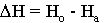
Once you know your pressure altitude (in feet), use this equation to find the absolute air pressure:
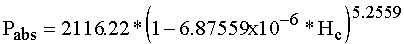
where Pabs is the absolute air pressure in lb/ft2 and Hc is the pressure altitude in feet.
If you are calibrating an airspeed indicator, don't worry about the absolute pressure, because the airspeed indicator is a differential pressure gauge.
Set the altimeter under test to 29.92 and record the reading. Tap the altimeter to eliminate as much friction as possible. This is your first data point (compared to the ambient pressure altitude). Connect the altimeter to the vacuum hose.
Now loosen the binder clip on the open end of the manometer tube, and lower the open end to raise the altitude on the altimeter (or raise the open end to lower the altitude). Tap the altimeter, and stop every 100 feet or so. Mark the height of the water columns on both sides of the board on the masking tape, and label the marks with the approximate altitude indicated. Record on your data sheet the altimeter reading. This is more easily done if you can get a buddy to help you. One person taps and records the altimeter reading; the other works the manometer tube. When you can't lower the open end any more, you can raise the altimeter end, until it can't go up any more. Continue to alternate until all of the readings are taken.
It is VERY important that the readings be recorded both moving up to the altitude and moving down to the altitude. Because of unavoidable friction, the reading obtained going up to an altitude will always be lower than the reading obtained coming down to an altitude. Think of it as the friction keeps the needle from quite getting all of the way to the proper reading. This effect is called hysteresis. How do we account for this? By averaging the errors going up and down at the altitude of interest.
The procedure for calibrating the airspeed indicator is very similar. Be sure to connect the manometer to the total pressure (Pitot) side of the airspeed indicator. Leave the static side open to the atmosphere. Raise the open end of the manometer to increase airspeed. Be sure to record data going up to airspeeds and coming down to airspeeds.
After finishing all of the data points, the instrument may be disconnected, and the heights of the marks can be read on the tape measure. Try to read the heights to the nearest 16th of an inch.
To determine the instrument correction, follow this process at each altitude tested:
1. Determine  H.
H.
| H | difference in water column heights (inches) |
| Ho | height of open end (inches) |
| Ha | height of end attached to altimeter (inches) |
2. Determine P.
![Delta P = rho[water] * g * Delta H/12](dpeqn.gif)
| P | pressure difference due to difference in water column heights (lb/ft2) |
![rho[water]](rhowater.gif) | density of water = 1.938 slugs/ft3 |
| g | acceleration of gravity = 32.2 ft/sec2 |
| H | from previous step |
3. Determine test absolute pressure at the altimeter.
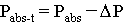
| Pabs-t | test absolute pressure at altimeter (lb/ft2) |
| Pabs | Ambient absolute pressure (lb/ft2) |
| P | from previous step |
4. Determine true pressure altitude.
![h[c] = (1 - (P[abs-t]/2116.22)^(1/5.2559))/6.87559x10^-6](hceqn.gif)
| Hc | true pressure altitude (ft) |
5. Determine instrument correction.
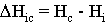
| Hic | altimeter instrument correction (ft) |
| Hc | from previous step |
| Hi | indicated pressure altitude (ft) |
6. Average instrument correction from increasing altitude reading and decreasing altitude reading.
7. To determine actual pressure altitude, add the instrument correction to the indicated pressure altitude.
1. Same as for altimeter.
2. Same as for altimeter.
3. Determine calibrated airspeed:
![V[c] = sqrt((1/rho[sl]) * 7 P[sl] * (((Delta P/P[sl]) + 1)^(1/3.5) -1))](vceqn.gif)
| Vc | calibrated airspeed (ft/sec) |
![rho [sl]](rhosl.gif) | density of air at sea level = 0.0023769 slugs/ft3 |
| PSL | pressure of air at sea level = 2116.22 lb/ft2 |
4. Determine instrument correction.
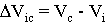
| Vic | airspeed indicator instrument correction (ft/sec) |
| Vc | calibrated airspeed (ft/sec) |
| Vi | indicated airspeed (ft/sec) |
5. Average instrument correction from increasing airspeed reading and decreasing airspeed reading.
7. To determine calibrated airspeed, add the instrument correction to the indicated airspeed.
| Pressure Altitude | 2500 ft |
| Pabs | 1931.897 lb/ft2 |
| H | 15.5 inches |
| P | 80.60 lb/ft2 |
| Pabs-t | 1851.297 lb/ft2 |
| Hc | 3654 ft |
| H | 5.0 inches |
| P | 26.00 lb/ft2 |
| Vc | 147.6 ft/sec |
| Vc | 101 mph |
| Vc | 87 knots |
mph = (ft/sec) * (3600/5280)
knots = (ft/sec) * (3600/6076)
Go to Top
The manometer can also be used to apply a controlled pressure to the Pitot static system to check for leaks. Just connect it at the port end instead of the instrument.
Figures 2 and 3 show the calibration data for one of the altimeters and airspeed indicators I used on my research project. Note that although the data looks scattered, it really is repeatable. Your's will probably look similar to this.
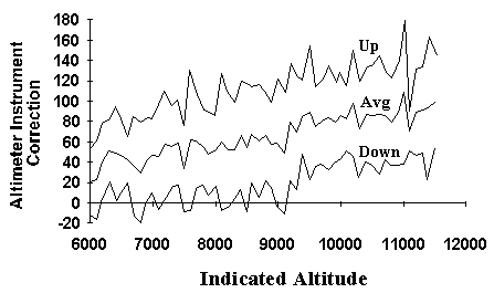
Figure 2. Altimeter Instrument Correction hic
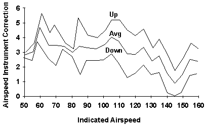
Figure 3. Airspeed Instrument Correction Vic
 EAA Chapter 1000 Home Page
E-Mail: Web Site Director Russ Erb at erbman@pobox.com
EAA Chapter 1000 Home Page
E-Mail: Web Site Director Russ Erb at erbman@pobox.com
 Formed in 2009, the Archive Team (not to be confused with the archive.org Archive-It Team) is a rogue archivist collective dedicated to saving copies of rapidly dying or deleted websites for the sake of history and digital heritage. The group is 100% composed of volunteers and interested parties, and has expanded into a large amount of related projects for saving online and digital history.
